


Nächste Seite: The Power Supply
Aufwärts: AH PRE-1 Highend-Preamplifier Development
Vorherige Seite: The Phono Preamplifier
Inhalt
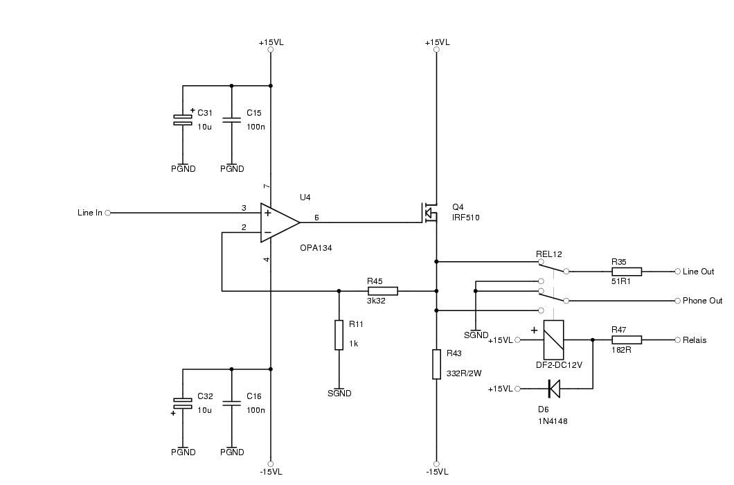
The listening tests of the single ended class A output stage of the
phono preamplifer were very promising, so I did not test different
circuit variations of the line level amplifier. I just copied the
circuit of the second stage of the phono preamplifier and did the
following changes (see the schematics in figure 3.1 on
page ![[*]](/images/latex2html/crossref.png) ):
):
- Instead of the active filter we set a linear amplification3.1 of approximately 10 dB using resistors
 and
and  . The
operational amplifier must be compensated for an amplification of
1 (0 dB), as the resulting input capacitance of the Mosfet and the
open loop output impedance of the operational amplifier form a lowpass
filter which turns the phase and decreases the loop stability. Counting
on earlier experience I chose OPA134-its sound is very good and it
has high impedance FET inputs with very low input quiescent current,
which allows us to use a high impedance volume pot.
. The
operational amplifier must be compensated for an amplification of
1 (0 dB), as the resulting input capacitance of the Mosfet and the
open loop output impedance of the operational amplifier form a lowpass
filter which turns the phase and decreases the loop stability. Counting
on earlier experience I chose OPA134-its sound is very good and it
has high impedance FET inputs with very low input quiescent current,
which allows us to use a high impedance volume pot.
- The quiescent current running through the Mosfet is increased to 45,5
mA to be able to drive the head phone. The dissipated power of
 and
and  is 680 mW each.
- The heat sinks for the Mosfet and the voltage regulators are bigger
due to increased power dissipation.
- The headphone is connected directly, while the output to the power
amplifier is connected via a 50
 resistor.
- A high quality volume pot is connected to the input of the line level
stage.
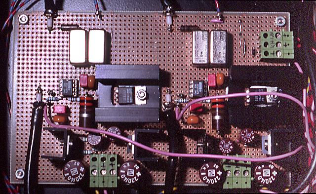
A top view of the printed circuit board
is in figure 3.2 on page .
Nächste Seite: The Power Supply
Aufwärts: AH PRE-1 Highend-Preamplifier Development
Vorherige Seite: The Phono Preamplifier
Inhalt
ah@despammed.com
![\includegraphics[%
width=1.0\textwidth]{line_sp_tex.ps}](img75.png)
![\includegraphics[%
width=1.0\textwidth]{pre1-line_tex.ps}](img76.png)